|
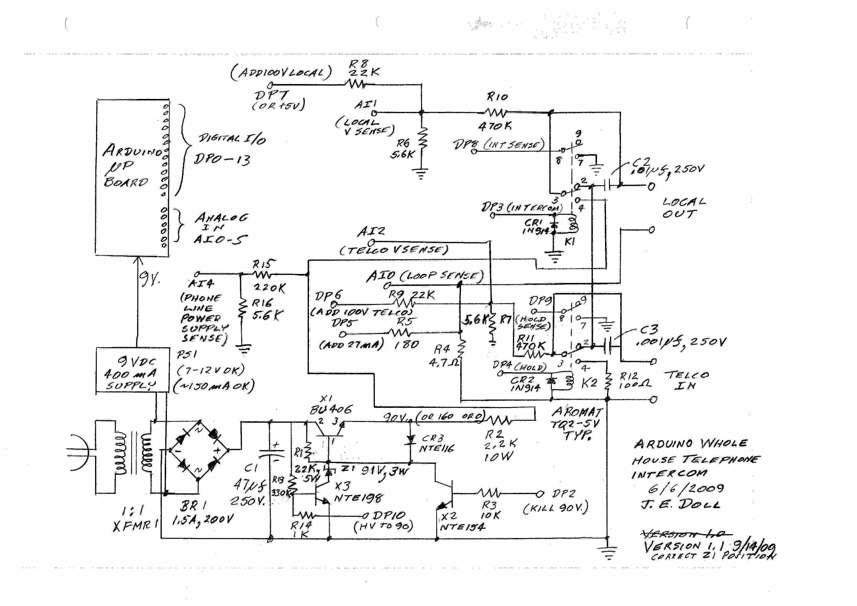
Arduino Whole House Telephone IntercomCircuit Description and Software Requirements Overview: The essence of the design is two relays, used to effect intercom and call hold connections, respectively, and a phone line power supply, all operated under microprocessor control. Several resistors facilitate feedback to the microprocessor. The feedback enables the processor to measure important parameters, thereby detect significant events, (like hook switch flashes,) and respond accordingly.
Note: Arduino board ground should be connected to the ground of the schematic. Errata: Zener diode Z1 should be in the collector lead of X3, below the junction of R1/CR3/X2 Collector. It appeared above that junction in schematic version 1.0. Phone Line Power Supply: The phone line power supply provides both ringing voltage and talk current to the Local line when the intercom is in operation. Household power is transferred through isolation transformer XFMR1, rectified by bridge circuit BR1, and filtered to approx. 160 VDC by C1. Note this voltage is unregulated, and will vary with household power level. R1 provides base bias current to transistor X1, turning it on. For talk current operation, the processor turns on transistor X3 via DP10 and R14. This effectively grounds the bottom of zener diode Z1, setting the base voltage of X1 to 91 VDC, a regulated value. Approximately 90 VDC appears at the emitter of X1. This is applied to the Local line via R2. R2 limits maximum talk current to about 40 mA. Divider R15/R16 scales the phone line supply voltage down to the range of an analog processor input. When ringing voltage is desired, the processor turns off X3 via DP10 and R14. This allows the base of X1 to rise to a level very near that of the unregulated high voltage. In turn, nearly the full high voltage level appears on the emitter of X1. After about 25 mS, the processor turns on transistor X2 via DP2/R3. This effectively grounds the base of X1, causing its emitter voltage to fall to near 0. Any capacitively held Local line voltage is quickly discharged through CR3. After another 25 mS (for 20 Hz ringing frequency) the processor turns X2 off, and voltage again goes very high. The processor should toggle DP2 at the ringing frequency and hold DP10 low while ringing, then revert to talk voltage conditions (DP10 high, DP2 low) during the silent period between rings. Normal (Transparent) Operation: One side of the Telco line is arbitrarily considered "ground" level. It is connected to the ground side of the Local line via R4, a small current sensing resistor. The Local side of R4 is connected to an analog input. By measuring this voltage, the processor can determine local loop current. A digital output, when driven high, injects additional positive current into R4 via R5. This biases the loop sense input, so that negative loop currents may be measured. (R5 could alternatively be connected to +5V, but I chose to make the additional current programmable.) The other ("hot") side of the Telco line passes through contacts 3->2 of relay K2, then 2->3 of relay K1, to connect to the hot side of the Local line. Resistive dividers R10/R6 and R11/R7 produce a scaled fraction of Local and Telco line voltages, respectively, at suitable magnitude for analog input to the processor. R8 and R9 inject additional positive current into the Local and Telco sensing nodes, respectively. Similarly to R5, the resulting bias permits negative line voltage values to be measured. In Normal mode, the processor must monitor for hook switch flashes, and respond as described in the description of other modes. Intercom Mode: While in Normal mode and on hook, the processor must monitor for an off hook flash. When loop current rises above about 15 mA (or below -15 mA), for a period of 200 mS to 2 S, then reverts to low level, an off hook flash is indicated. For confirmation, voltages can be verified to drop to a few volts (say 15 V or less, absolute value) during the flash. The processor should then activate relay K1 by setting DP3 high. Diode CR1 absorbs any potentially damaging inductive voltage spike when drive to K1's coil is subsequently turned off. The processor can verify that K1 has activated by verifying DP8 is connected to ground via K1 pins 8->7. K1 disconnects the hot side of the Local line on pin 3, from the hot side of the Telco line on pin 2, and connects it instead to the internal phone line power supply on pin 4. When intercom mode begins, all local phones are on hook. The processor should control the phone line power supply to produce ringing voltage, while monitoring line current and voltage for an off hook condition. When an off hook condition occurs, the processor should set the power supply to talk voltage level, and monitor for a subsequent on hook condition. If an external call comes in while talking in Intercom mode, capacitor C2 couples enough of the Telco ringing voltage to the Local line that it can be heard in the earpiece. C2 also couples high frequency, out of band signals to the Local line, so possible DSL operation will not be interrupted. When on hook is detected, the processor deactivates relay K1, reverting to Normal mode. I also included a ringing timeout. If no phone goes off hook after 2 minutes of ringing, the intercom gives up and reverts to Normal mode. Intercom/Hold Mode: While in Normal mode and off hook, the processor must monitor for on hook flashes. When a flash occurs, and if a double flash does not occur, (see below,) the processor enters Intercom/Hold mode by activating both relays K1 and K2. It can verify activation of K2 by confirming DP9 is connected to ground via K2 pins 8->7. Since the Local line is off hook when entering Intercom/Hold mode, the phone line power supply should initially be set for talk current. Relay K2, activated via DP4, disconnects the Telco line from K1 via pins 3->2, and instead connects a 100 ohm load resistor, R12, across the Telco line via pins 3->4. This simulates an off hook condition for the Telco line. Capacitor C3 continues to couple high frequencies to the Local line via C2, assuring uninterrupted operation of DSL service. While in Intercom/Hold mode, the processor monitors hook status. When on hook, it should generate the ringing cadence. When off hook, it should enable talk current. Hook status may be cycled several times during Intercom/Hold mode. Each time, the power supply should be set to ring or talk appropriately. When an on hook flash occurs, the processor should deactivate K1 and K2, and revert to Normal mode. Again, a ringing timeout can revert the intercom to Normal mode if nobody answers within 2 minutes. If this happens, the outside call will be dropped. Remembering that an on hook flash of the Telco line may activate a special phone company function, special care must be taken while monitoring for on hook flashes. The intercom will take a double flash (a second flash that begins within 2 seconds of the end of a first flash) to activate the phone company feature. (If you don't like this solution, you can adopt another, or eliminate Intercom/Hold mode altogether.) While monitoring for on hook flashes in Normal mode, the processor should immediately activate relay K2 (the hold relay) when the Local line goes on hook. When either a flash is detected or maximum flash time elapses, the relay should be released. This procedure will block local flashes from being passed through to the Telco line. When a double flash is detected, the processor should generate a Telco on hook flash by releasing K2, and activating K1 for about 750 mS, and remain in Normal mode. |