|
Arduino Whole House Telephone IntercomBuilding the Intercom I hand wired mine, mounting small components on perf board with connector headers to plug into the Arduino in "shield" fashion. I drilled holes in the perf board to expose LEDs on the Arduino board below while debugging. If you lay out a PC board for the shield, I would like to hear about it. My unit uses an isolation transformer, larger than necessary, and an off-the-shelf 9 VDC "wall wart" type power supply for the Arduino. If you have trouble finding a suitable isolation transformer, you can use two transformers with 12.6 VAC secondaries. Connect the secondaries together, and run the second transformer backwards. This worked OK for the non-Arduino intercom version.
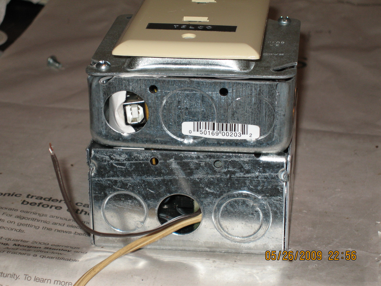
For an enclosure, I used a 4-inch square (outside dimension) metal electrical junction box 2 inches deep, coupled to a 1.5-inch deep extension. The isolation transformer is mounted on the rear of the enclosure, and near its right side, via drilled holes and #10-32 screws and nuts. The 9 VDC supply is affixed to the transformer frame with mounting tape, and powered from the isolated winding. The power cord exits through a knockout hole in the bottom. The Arduino and shield is positioned along the front of the left side, with its USB connector exposed through a knockout hole in the bottom. It is also possible to view the pin 13 and power LEDs through the knockout. This arrangement facilitates software updates without disassembly. An insulating sheet, cut from 3x5 inch index card material, ensures the wiring side of the Arduino will not inadvertently contact the enclosure. A cover with a singlewide opening holds a terminating plate with two 8-pin modular jacks. Transistor X1 must dissipate a few watts when supplying talk current. It needs a good heat sink to prevent overheating. The metal enclosure itself makes a good heat sink. It is preferable not to mount X1's tab in electrical contact with the enclosure, since it may be at a potential of nearly 200 V with respect to circuit ground. I mounted mine to the top of the box near the front through a hole with a #4-40 screw, nut and washer, and using a thin insulating sheet (of mica, I believe) and insulating washer. These insulating parts are often supplied with TO-220 packaged transistors. Be sure to coat all mounting surfaces (both sides of the insulating sheet, the transistor tab and the enclosure inner wall) with non-conductive thermal grease. After lengthy talk current operation, (worst case for power dissipation,) the top of the box near X1 becomes an uncomfortably hot resting place for a finger. X1 connects to the Arduino shield via a 3-wire cable. Some other components, notably R1 and R2, get hot in operation. However, they are rated to handle expected power and should not cause a problem. If it is easier, you can build these of two or three parts of lower power rating and equivalent total resistance. I brought an extra pair of wires out the bottom, which, when connected, jumper the internal telephone line power supply to the hot side of the Telco connector. This can be useful for test and debugging purposes, when you want to operate with no Telco line connected. If you do this, use insulating tape to make sure the wires do not contact the enclosure or other circuitry. Also, be sure to DISCONNECT THE POWER SUPPLY JUMPER BEFORE CONNECTING AN EXTERNAL TELCO LINE. Before firing up your newly built circuit, I recommend exercising and verifying it, without 115 VAC connected at first, with this code. |