|
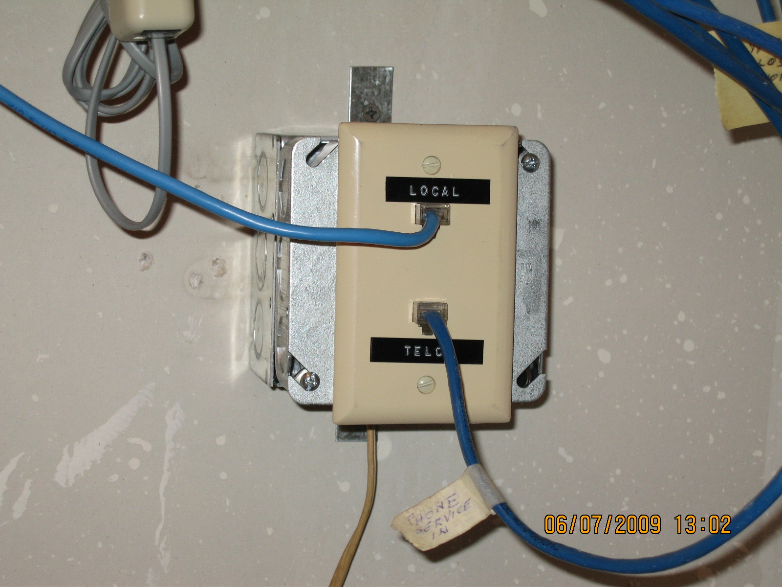
Arduino Whole House Telephone IntercomInstalling the Intercom The intercom has two connectors. One is labeled "Telco", the other "Local". Identify a good place to cut your existing telephone line so as to connect the incoming line to the Telco connector, and the premises wiring to the Local connector. Then plug the intercom into household power. Thereafter, all telephone instruments connected to the Local side will participate in the intercom function.
If you are not sure where to break in to your telephone line, a good place to look is at the junction box where Telco wiring is connected to premises wiring. At our house, this is on an exterior wall. You could connect the intercom right there, but an internal location is more convenient. Trace the premises wiring to a convenient place. We keep one telephone instrument, our answering machine, connected to the Telco side of the line. Thus, the answering machine can pick up an incoming call even if we are talking on the intercom at the time. If multiple telephone lines enter your premises, the intercom can be installed on just one. At our house, that is our main voice number. All lines typically run in a single cable. Our cable has four lines. Each individual telephone line comprises two physical wires, bundled within the cable as a twisted pair. You only need to cut into the pair that will connect to the intercom. However, I found it convenient to terminate all four pairs from each side in a modular plug. Inside the intercom, the non-intercom pairs are wired straight through from the Telco jack to the Local jack. If you want to take the intercom out of service, it is easy to reconnect all phone lines via a straight-through coupler. In modular 8-pin connectors, telephone "line 1" (of four) is conventionally connected to pins 4 and 5, the "middle" two pins. Line 2 connects to pins 3 and 6, just outside the middle pins. Line 3 connects to pins 1 and 2, and line 4 connects to pins 7 and 8. Intercom Only Installation: It is possible to create an intercom system only, with no connection to an external telephone line. For this configuration, connect the internal telephone line power supply to the hot side of the Telco connector. CAUTION: Do not attempt to connect an external Telco line when the internal power supply is connected in this way! Software attempts to sense the presence of a power supply jumper, and avoid activating the Hold relay (K2, see circuit description,) or entering Intercom/Hold mode when a jumper is present. Activating K2 and applying ringing voltage would burn out the hold resistor, R12. For an intercom only system, you can leave out K2, the hold resistor, and the telco voltage sensing resistors altogether. |